Knowledge of the basics of installing electrical equipment should be possessed not only by qualified electricians. With the basic provisions for the assembly and operation of the electric box, which controls the supply of energy to all consumers in the apartment, it is better to familiarize themselves with homeowners.
Knowing how and in what sequence the electrical switchboard is disconnected, even an owner of an apartment or house who is far from electrical work will be able to quickly respond to a malfunction in the system - call an electrician or solve the problem on his own.
The purpose of the electrical panel
Externally, products in which protective and accounting equipment is installed look different. This can be a compact plastic box with tinted glass installed in the hallway, or a large metal shield mounted in a wall on a floor area.
We are talking about an electrical panel, which is necessarily present in residential buildings, office buildings, in production - wherever power lines are laid.

Electrical switchboards, depending on the place of installation and destination, can be distribution, group, accounting and distribution. For example, a box with a counter is called an accounting and distribution box, and a box in the hallway, in which only machines are located, is called a group box.
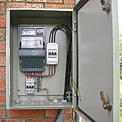
Possible installation locations are prescribed in the regulatory documentation, but largely depend on the purpose of the shield. For example, for private houses, one of the electrical panels, with an electric meter and an input device, is usually installed on the street, on a pole or facade.
Shield Features:
- reception of electricity from the central highway - a power line connected to the house;
- energy distribution by consumer groups or individual lines;
- protection of the mains from high loads and short circuits;
- quality accounting and stabilization of electricity;
- protection of power users from electric shock.
Simply put, the uninterrupted transmission of electricity to the house, the safety of all residents, and the safety of property will depend on the proper assembly of the electrical panel.
Compilation of an exclusion scheme
Calculate the size of the apartment or street shield and determine the choice of protective devices is possible only after drawing up a circuit or wiring diagram of the power supply of the house.
The main thing is to indicate all electrical appliances, lighting equipment and wiring devices, as well as their power, voltage and current strength.

The layout of electrical equipment is an example of a circuit according to which it is easy to calculate and select the content of the electrical panel. For convenience, the arrangement of furniture is indicated, as well as the height of installation
After preparing the wiring diagram, it is necessary to divide all the circuits into separate groups.
To do this, follow the principles:
Image Gallery
Photo from
Powerful appliances - electric ovens, washing machines and dishwashers, boilers and air conditioners - are connected separately. For each device, the power of which is more than 2 kW, a socket is output and an automatic machine is installed on the shield, selected according to the rating
Kitchen appliances - stove, oven, dishwasher, as well as a washing machine, water heater are connected with a NYM cable, but more often VVGng. Wires for lighting circuits will not work here, the minimum cable parameters are 3 * 2.5 mm². The rating of the machine on the shield is 16 A
It is much more convenient when all the outlets of one room are combined and connected to the same machine. If an emergency occurs on the power line serving the kitchen or living room, the circuit is easily disconnected and repaired. At the same time, in other rooms the power supply will remain
Like sockets, lighting circuits are divided into groups serving 1-2 rooms. If there are few consumers in the premises, then in one group you can combine the kitchen and the corridor, the bath and the hallway, the bedroom and the living room. The best cable option is VVGng 1.5 mm², automatic - 10 A
Separate sockets for powerful consumers
Cable for connecting powerful equipment
Outlet circuits distributed in rooms
Lighting lines are logically separated
Now they are producing very powerful equipment, so you should not rely on universal tips, it is better to study the installation requirements first. For example, for some ovens, the conductor cross-section should be at least 4 mm², and for water heaters - even 6 mm². Accordingly, you will need machines for 20 or 32 A.
Based on the foregoing, they make up the assembly diagram of the electrical panel.

A sample diagram showing all the wiring devices. Some machines are connected to RCDs. At the input - an introductory 3-pole circuit breaker, and after the counter a difavomat is installed
Installation of RCDs is mandatory, since without it the protection of the outlet lines is considered inferior. The same can be said about the allocated power circuits for powerful equipment - each device needs its own trip device.
Equipment ratings: rated current - one step more than that of the connected machine, differential tripping current - 30 mA.
All circuits related to the bathroom or bath, connect RCD with differential. current 10 mA. This may include individual lines on the underfloor heating, washing machine, sockets, shower.
The choice of electrical equipment
Before starting the installation, you need to buy the electrical panel itself and all electrical installations and devices that will make up its content. It should be borne in mind that each item occupies a certain amount of mounting space on a DIN rail - a 3.5 mm wide metal bar. One and several DIN rails can be located in one box.
Under one “mounting place”, a segment on a 1.75 cm long profile is considered - a module. The passport of the electrical panel must indicate how many modules it is designed for.

Three devices are fixed on one DIN rail: the first two occupy 3 modules, the third - one module. Leaving space between adjacent devices to save space is not recommended
Before choosing a shield, add up the number of all modules, and then add a few places to the resulting amount that may come in handy in the future. For example, we calculate which box is needed for a 1-room apartment.

According to the scheme, we determine how many modules each of their devices occupies: a 4-pole input circuit breaker - 4 places, a counter - 6, AWDT - 2 x 2, circuit breakers - 4. The result is 18 modules
For 18-20 places, an electrical panel for 24 modules is suitable. But if the apartment is large, and in the future it is planned to purchase new equipment, install a warm floor or repair with a replacement wiring, then it is better to purchase a box with 36 seats.
If you want to simplify further work, to maximize network protection, and the location of the modules convenient, try to choose a shield with a complete set, and this:
- removable frame with DIN rails;
- entry holes and cable holders;
- two tires, working and protective zero - with supports and installation sites;
- set of mounts for installation;
- organizers for wires.
Shields are metal and plastic, built-in and mounted.
Consider how they differ fundamentally.
Image Gallery
Photo from
Metal electrical panel for floor installation
Plastic box for residential use
Hinged shield for quick installation
Built-in flush shield
Experienced electricians recommend working with one store. The advantages of buying from a major supplier are a large assortment of goods and a guarantee of obtaining original products, not fakes. Therefore, it is better to purchase a shield and other electrical installation products in one place.
In addition to the meter and protective devices, you will need:
- multi-pole combs with end caps - for connecting modules to each other, simplifying installation and saving space;
- 2-3 meters of PV1 wire with a cross section, like that of the input cable, and color marking of insulation;
- zero buses or cross-modules for group RCDs;
- clamps and ties for the organization of conductors;
- DIN rail stops
- stubs to mask free spaces.
If financial opportunities allow, it is better to select the equipment of one trusted manufacturer - Hager, ABB, Legrand, Schneider Electric. Devices of one brand are easier to install, and the shield will look much more aesthetically pleasing.
Step-by-step installation and assembly instructions
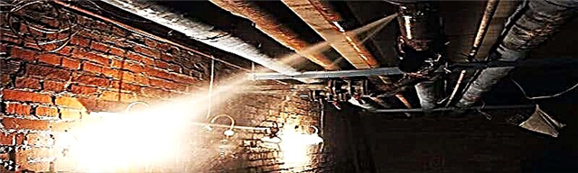
According to GOST and PUE standards, the boards should be located in a well-lit, ventilated room, the humidity level in which is not higher than 60%. Installation height - not less than 1.4 m, distance to jambs, angles - not less than 15 cm. Gas pipes should not pass nearby.
Mounting a hanging shield is no more difficult than a bookshelf - the structure is supported by dowels driven into the wall. Therefore, we consider the option of installing in a concrete or brick wall.
Stage 1 - wall mounting
Before installation, the electric box must be on hand so that you can clarify its dimensions, and in the future use the case for fitting.
We start with the markup - with the help of the level we draw a straight line indicating the place where the bottom of the box will be located. Then we apply the case, circle it with a marker on the contour.

We put on a protective mask, take a grinder with a 23 cm disc, a chisel cutter or other powerful tool and make cuts first along the designated contour, and then in the center
Next, we act as a puncher - we knock out pieces of concrete (or brick) between the cuts. Carefully align the inner surface of the niche using a hand chisel.
We try on whether the case enters a niche, if everything is fine, we fasten the mounting kit to it and insert it into place. We drill holes for the dowels, we fasten the dowel with nails.
There is a gap between the shield body and the wall - we fill it with alabaster or an alternative building mixture, and then mask it with the finish along with the rest of the wall surface.
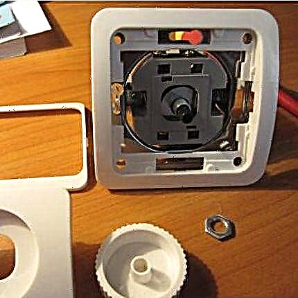
Stage 2 - cable entry and cutting
In modern electroboxes, holes for wires are provided. They are located on different sides, but not all need to be used. The desired holes are extruded along perforated lines. Their standard size is 16/20 mm, designed to enter a corrugated pipe, into which wires for insulation are placed.
Operating procedure:
- squeeze the plates or remove the plugs;
- we cut the corrugated pipe of the cables at the walls of the box;
- we lead the supply cable into the shield case so that it is near the fastener of the input machine, that is, in the upper left corner;
- we attach the cable to the eye or other fastening element, fix it with a tie;
- We mark by insulation or heat shrink.
We repeat all the steps with the rest of the cables leading to consumers.

A properly organized cable entry into the electrical panel looks something like this: power supply on the left, lines of the apartment network on the right. For ease of operation and assembly of modules, the frame is temporarily removed
As you know, all cables are protected by double insulation. The top layer for switching wires inside the electrical panel is not required, so it must be removed.
But on the other hand, additional marking of each wire will be needed, since after weaving the cores it will be difficult to guess which line leads to. For marking, we use masking tape, which is easily marked.

To cut the cable, remove the outer insulation, it is better to use a special knife with a heel. Unlike a conventional construction knife, it very carefully removes the polymer coating, leaving the inner shells intact
After cutting the cables, the shield is ready to install the already dialed frame. Usually, during the assembly process, finishing work is carried out, during which the inside of the case is better to cover.
To do this, use either a cardboard blank, which comes complete with a shield, or a self-cut cover.
Stage 3 - assembly of modules on the frame
For work, slotted and Phillips screwdrivers, a stripper, pliers, pliers, wire cutters, a hacksaw, a construction knife, a screwdriver, and a tester will be required.
The layout of the modules is carried out according to a linear or group scheme:
- linear - First put up the RCD and difavtomaty, then the device AB;
- group - first the RCD / difavtomat, then the machines connected to it, again the RCD, etc.
The following article, which details this difficult question in detail, will familiarize you with the differences in the device and the operating principles of RCDs and diflattomats.
The first option is easier to install, and the second is more convenient when you need to find a problem on the network. It should be remembered that the wires enter from above, exit from below. The cross-section of the conductors inside the box and outside must match. It is advisable to connect devices with solid pieces of wires, and not combined from different segments.
Assembly Instructions:
Image Gallery
Photo from
We arrange the modules on the frame as they should be in the shield. The standard sequence is: an input automaton - a counter - group RCDs / differential machines - automata. So that the devices do not move apart during installation, we install limiters on the edges of each row
We check again whether the ratings are correctly calculated and the devices are divided into groups. If a voltage relay is installed, then its place is in front of the RCD. After checking, we fix the devices on the DIN rails by tightening the fixing screws
We prepare 1-pole and 2-pole combs: we cut the fragments of the required length, close the ends with plugs. We connect the combs to the wires by means of universal terminals guaranteeing tight contact. Tighten the connection
From the introductory machine to the RCD, difavtomatov and single machines it is necessary to distribute the "phase". To do this, we use pieces of wire that should connect the device freely, without tension, but also without excess volume
The working "zero" wire leads from the input machine to the zero terminals of the RCD. It is better to use standard marking, that is, a wire in blue insulation. Group RCDs are connected to zero tires, to save wire space we tighten the ties
We collect the yellow-green wires of the three-core cables in bundles and direct them to the protective zero bus. We also ground the electrical panel if it is made of metal. Using a PLZ screwdriver or a screwdriver with the same tip, tighten all connections
To check the correct connection, we test: we supply electricity to the input device, and then turn on all the devices in turn. Those on which the "test" button is located, check for functionality
To check the voltage in the network, we use a tester or multimeter. We bring the probes first to the input terminals of the protective devices, and then to the output. If all the machines and RCDs are serviceable, disconnect them from the power supply.
Step 1 - modular devices on the frame
Step 2 - Modular Device Ratings
Step 3 - combs for connecting machines
Step 4 - wires for the distribution of the "phase"
Step 5 - wires for distributing "zero"
Step 6 - connecting the ground to the bus
Step 7 - Instruments with a Test Button
Step 8 - tester to check the connection
The frame is assembled, it remains to install it in the body of the electrical panel and make a connection to the power cable and consumer wires.
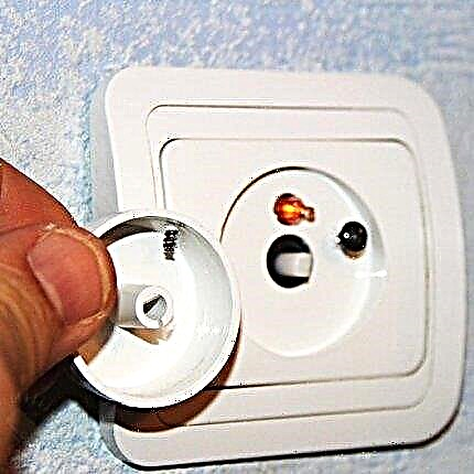
Stage 4 - loop connection and test
The frame, which is completely ready for operation, must be inserted into the hinged or wall-mounted housing. This stage is carried out only after the mortar has dried, and better - at the end of all finishing work.
We proceed according to the plan:
- Turn off the power of the shield, let others know so that they do not accidentally connect it (in words or using a tablet).
- We remove the protective cover and debris that has fallen into the case, bend the wires up into the box.
- We insert the assembled frame, fix it with screws.
- We mount two tires - N and PE, and the second is better to fix where the wires go, for example, from below.
- We distribute the wires according to their purpose (separately phase, neutral and earth), we fasten the group with ties.
- The yellow-green wires of the earth are sent to the PE bus, we leave a small margin, mark and connect.
- Groups of blue wires of working zero are sent to the buses of group RCDs, marked and connected.
- The remaining blue wires and zero input cable lead to a common bus, mark and connect.
- We direct the phase wires to the modular devices, trying to get on the other side opposite the zero cables. We mark, connect to the contacts of the circuit breakers AB and difavtomatov.
- The input cable is brought to the upper terminals of the input machine, we connect.
The connection to the buses is relevant if not previously made directly in the frame. After connecting all the conductors with the corresponding bus terminals or modular devices, we check, tighten the fasteners.
All devices on the electrical panel must be in the off state before commissioning. In this case, all electrical installations in the apartment - lighting, household appliances, sockets - must be brought into operation.

The first step is testing the introductory apparatus with a multimeter. After applying voltage, we check its presence, and then the correspondence of zero and phase
We carry out alternate connection of machines and RCDs, test using a special button and turn it on again after disconnecting. We turn to the machines, check if there is voltage at the input terminals. Then turn them on and check the voltage already at the output.
Last of all, we check the operation of leased lines for powerful equipment. We turn on the oven, washing machine, air conditioning, and monitor the operation of the appliances. If the result is satisfactory, we hang the door and lock the electrical panel.
Video # 1. Option to build an electrical panel:
Video # 2. Assembly instructions and recommendations for a shield for 72 modules:
You can assemble the electrical panel yourself, but checking the installation and connection by a qualified electrician is mandatory. Without a corresponding conclusion, the organization supplying the house with electricity will simply block the line.
Want to talk about your own experience in conducting electrical work? Do you have useful information that could be useful to independent beginner electricians? Please write comments in the block below, post photos and ask questions about the topic of the article.