Grounding is used in the implementation of various projects of electrical systems. The very concept of "grounding" is schematically considered by connecting a section of an electrical circuit to the earth's potential.
The ground loop contains a conductor and an electrode embedded deep in the ground. The traditional action in electrical practice is to measure the grounding resistance of networks that are still being launched and are already in operation. We will describe how and how this important action is performed.
What are measurements necessary for?
The brilliant solution to the following tasks is achieved by perfect zero resistance in the grounding circuit:
- Prevent voltage on the case of technological machines.
- To achieve an effective reference potential of electrical equipment.
- Completely eliminate static currents.
True electrical engineering experience shows: it is impossible to get a result at a perfect zero.
The procedure for making the necessary measurements using the device to determine the resistance of the grounding bus. Such procedures are carried out on a schedule approved by the management of the service organization.
In any case, a grounded electrode produces any resistance.
The specific value of resistance is determined by:
- electrode resistance at the point of contact with the conductive bus;
- the contact area between the earth electrode and the ground;
- soil structure giving different resistance.
The practice of measuring the resistance of the ground loop indicates that the first two factors can be neglected, but subject to logical conditions:
- The ground electrode is made of highly conductive metal.
- The body of the electrode pin is carefully cleaned and firmly planted in the ground.
The third factor remains - the resistive surface of the soil. It is seen as the main design part for measuring the resistance of the ground loop.
It is calculated thanks to the formula:
R = pL / A,
where: p is the soil resistivity, L is the conditional deepening, A is the working area.
To protect the owners of the house / apartment, all types of powerful home electrical equipment must be equipped with grounding:
Image Gallery
Photo from
All types of household volatile equipment operated in apartments and houses must be connected to autonomous or public grounding systems
To connect electrical appliances to the grounding system, it is necessary to install sockets with grounding contacts equipped with either copper brackets extending outside the case or a third hole designed to immerse the contact of the plug with three pins
All types of refrigeration equipment (refrigerators, freezers, MVPs, electric stoves, washing machines) are subject to mandatory grounding
Connection to the grounding circuit must be carried out according to the scheme applied by the manufacturer of technical products, using the means recommended by him
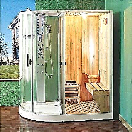
It is imperative to ground the hot tub, as electric appliances are used in her work
Unquestioning grounding is required for all types of network machines, from a home desktop computer to server cabinets, including electrical cabinets for machines and RCDs
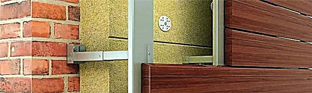
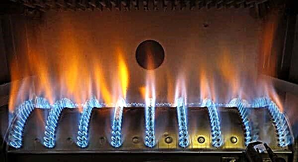
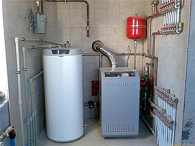
It is necessary to ground all models of volatile gas boilers: both floor and wall
All grounding lines are laid in parallel; serial connection to the grounding system is unacceptable
Grounding contact options
Socket with earthing contact
Grounding kitchen appliances
Connecting the washer to the ground loop
Hot tub earthing device
Grounding method of network equipment
Grounding of a floor gas boiler
Connecting ground lines to the bus
When testing resistance, each of the grounding lines is checked separately. The resistance between the grounding element and each non-conductive part of the electrical equipment, which may be under voltage, should be less than 0.1 ohms.
Overview of measuring methods
There are several options for measuring the resistance of the ground loop, each of which quite accurately allows you to determine the desired value.
3-point detection system
So, for example, a 3-point circuit technique is often applied based on the effect of a potential drop.
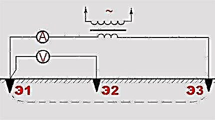
A graphical diagram of the so-called three-point system, which is often used when it is necessary to measure the resistance value of the ground loop
Measurements are carried out in three main steps:
- Measurement of voltage at the electrode E1 and probe E2.
- Measurement of current strength on the electrode E1 and probe E3.
- Calculation (by the formula R = E / I) of the resistance of the grounding electrode.
For this technique, the accuracy of the measurements is logically dependent on the installation location of the E3 probe. It is recommended to introduce it into the soil at a distance - optimally outside the so-called area of ESE (effective resistance of electrodes) E1 and E2.
Measurements on the technology "62%"
If the soil structure for the placement of the grounding electrode differs in homogeneous contents, the “62%” method for determining the resistance of ground loops promises good performance.
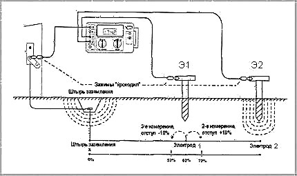
The scheme for the measurement technology under the interesting name "62%". However, the name is taken from the optimal spacing between the electrodes, at which an acceptable result is obtained.
The method is applicable to circuits with a single grounding electrode. The accuracy of the readings here is due to the possibility of the location of the working probes in a straight section, relative to the grounding electrode.
Control probe installation points
| Electrode deepening, m | Distance to probe E1, m | Distance to probe E2, m |
| 1,8 | 13,7 | 21,9 |
| 2,4 | 15,25 | 24,4 |
| 3,0 | 16,75 | 26,8 |
| 3,6 | 18,3 | 29,25 |
| 5,5 | 21,6 | 35,0 |
| 6,0 | 22,5 | 36,6 |
| 9,0 | 26,2 | 42,65 |
Simplified point-to-point method
The use of this measurement method requires the presence of another high-quality grounding in addition to the one that will be studied. The technique is relevant for densely populated areas, where it is often not possible to widely operate auxiliary working electrodes.
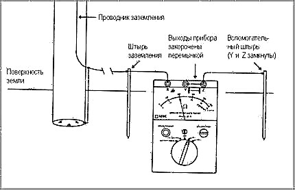
A simplified measurement procedure is carried out according to a two-point scheme. With this technology, less manipulation of equipment and calculations is required, but the accuracy of the calculations is low
The point-to-point measurement method is different in that it simultaneously shows the result for two grounding devices connected in series. This explains the requirements for high quality performance of the second grounding, so as not to take into account its resistance.
To perform the calculations, the resistance of the ground bus is also measured. The result obtained is subtracted from the results of general measurements.
The accuracy of this method leaves much to be desired in comparison with the two above. Here, the distance between the ground electrode plays an important role, the resistance of which is measured by the second ground. By default, this technique is not applied. This is a kind of alternative when you cannot use other measurement methods.
Accurate Four Point Measurement
For most resistance measurement options, the 4-point technology is considered the most optimal way, in addition to 2-and 3-point ones. Such measurement technology is endowed with instruments similar to the tester of the 4500 series. Judging from the name of the method, four working electrodes are placed in one line and at equal distances on the working platform.
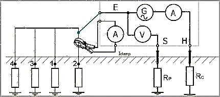
According to this four-point scheme, the most accurate measurements are made. Modern equipment is used and it is possible to perform work without disconnecting the grounding circuit
The current generator of the device is connected to the extreme electrodes, as a result of which a current flows between them, the value of which is known. At the other terminals of the device, two internal working electrodes are connected.
These terminals have a voltage drop value. The final measurement result is ground resistance (in ohms), the value of which the device displays on the display.
4500 Series instruments are often used to measure touch voltage. Using a special module, the device generates a small voltage in the ground - an imitation of cable damage.
At the same time, the current flowing through the ground circuit is indicated on the scale of the device. The readings on the screen are taken as a basis and multiplied by the estimated value of the current in the earth. In this way, the touch voltage is calculated.
Implementation of measures to monitor the state of electrical equipment and grounding lines. For work the measuring device like 4500 is used
For example, the maximum value of the expected current in the fault area is 4000A. A value of 0.100 is indicated on the screen of the device. Then the value of the touch voltage will be 400V (4000 * 0.100).
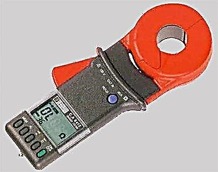
Measurement with the instrument S.A6415 (6410, 6412, 6415)
The uniqueness of this method is the ability to take measurements without disconnecting the grounding circuit. It should also be emphasized the advantageous side when measuring the total resistance of the grounding device is permissible by the method of including the resistive component of all connections in the grounding circuit.
The principle of operation is approximately as follows:
- A special transformer in the circuit creates current.
- Current flows in an educated circuit.
- Using a synchronous detector, the measured signal is recorded.
- The received signal is converted by the ADC.
- The result is displayed on the LCD.
The device is equipped with a module (selective amplifier), thanks to which the useful signal is effectively cleaned of various kinds of interference - and h. noise. The paws of ticks in their articulated state form an excited circuit, covering the ground conductor.
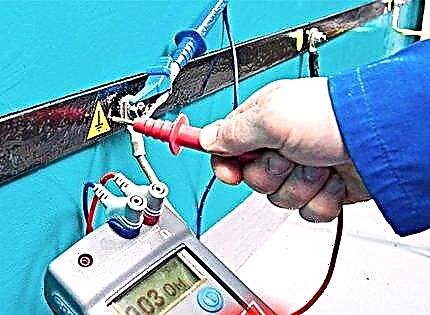
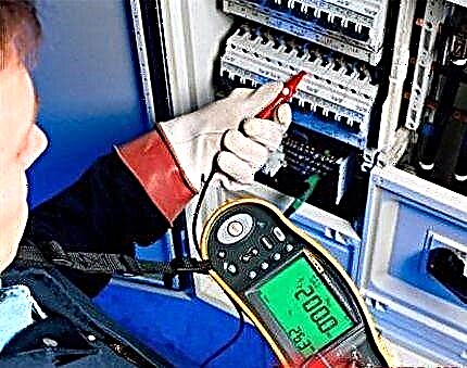
Instructions for measuring with a device S.A6415
The sequence of actions when working with the device of the C.A6415 series is clearly described in the instructions that came with this unique device.
A unique measuring device is pliers, thanks to which it is relatively simple and easy to measure the resistance of the earth contour in various conditions
For example, there is a need to measure the grounding resistance of an electrical module (transformer, electric meter, etc.).
Sequencing:
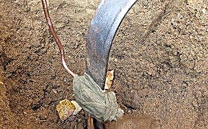
- Open access to the grounding bus by removing the protective cover.
- Grab the grounding conductor (bus or directly electrode) with the pliers.
- Select measuring mode “A” (current measurement).
The maximum current value of the device is 30A, therefore, if this figure is exceeded, measurement cannot be performed. Remove the instrument and try again at another point.
The process of taking measurements using measuring devices of type C. A6415 and 3770. The measurement results are recorded in the table and compared at the next maintenance
When the current value obtained on the scale falls within the permissible range, you can continue to work by switching the device to measure the resistance "?".
The result displayed on the display will show the total resistance value, including:
- electrode and ground bus;
- neutral contact with the ground electrode;
- contact of the connections on the line between the neutral and the ground electrode.
When working with pincers, it should be borne in mind: the overestimated readings of the device regarding grounding resistance are usually due to poor contact of the grounding electrode with the ground.
Also, a torn current-carrying bus may be the cause of high resistance. High resistance values at the connection points (splices) of the conductors can also affect the readings of the device.
General guidelines for measuring USG
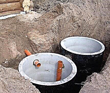
Before constructing a grounding circuit, for example for a gas boiler, it is necessary to obtain accurate information about in which area the grounding electrode will be laid. Often, it is proposed to refer to the existing tables to determine the “p” values of the soil.
However, this option with tables provides purely indicative data. Therefore, you should not rely on them. True values of soil resistance can vary significantly.
Option # 1: single layer primer
If the soil has a homogeneous component, its resistivity is measured by the method of "test electrode".
The structure of a homogeneous soil. Under such conditions, measuring and calculating resistance is much simpler than doing the same work on multilayer soils.
The method involves performing a certain procedure in two stages:
- Take a rod control probe with a length slightly greater than the depth of the design tab.
- Immerse the probe in the ground strictly vertically to the depth of the project bookmark.
- The end remaining above the surface of the earth is used to measure the spreading resistance (Rr).
- USG is determined by the formula p = Rr * Ψ.
It is advisable to perform the procedure several times at various points on the job site. Alternative measurements help to achieve accurate soil resistance measurements.
Option # 2: multi-layer soil
For such a situation, the USG is measured by the method of stepwise sensing. That is, the control probe is immersed to the working depth in steps, and in the position of each step, resistivity measurements are performed. Calculations of average USG are made using formulas for each individual measurement.
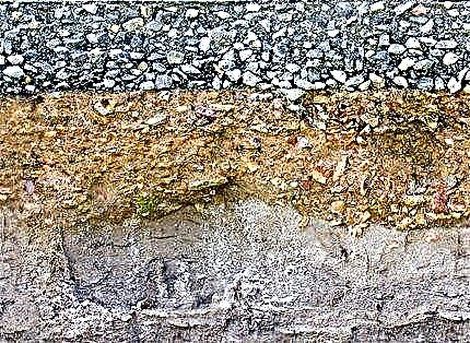
Multilayer soil. Under such conditions, it is necessary to calculate the resistance of each individual layer. Multilayer soil calculations require more work
Then, based on the climatic characteristics of the area, they find the values for seasonal changes. In this way (quite complicated), the calculated values of the UGS of the upper layers are obtained. The underlying layers are considered as not subject to seasonal changes and therefore the calculation for them is limited to a somewhat simplified measurement and calculation.
Performance Requirements
Work of this kind, of course, is carried out by qualified personnel representing specialized organizations. So, utilities are usually responsible for the operation of power panels in residential buildings. To make any measurements at these points is allowed only through access to these services.
Electrical circuits are hazardous systems. Despite the fact that household communications are designed for voltages less than 1000V, this voltage is fatal to humans. All necessary safety precautions must be observed when handling electrical equipment. The layman often does not know such measures.
The following article, which contains the rules and guidelines for the work, will familiarize you with the features of the grounding structure for a bathtub in a city apartment.
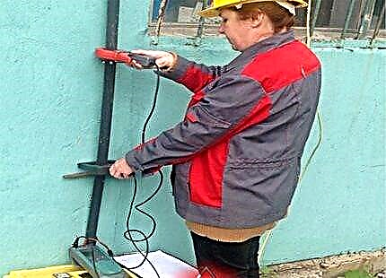
Taking measurements in practice using the instrument:
The execution of work related to the verification of grounding resistance is required, regardless of the complexity of the electrical circuit and the category of the facility where electrical equipment is installed or installed and operated. Many specialized organizations are ready to provide such services.
Please leave comments in the block below. It is possible that you know a simple and effective way to measure the resistance of ground loops, not given in the article. Ask questions, share useful information and photos on the topic.